Content still not complete. This page needs editing. Come back often for new content.
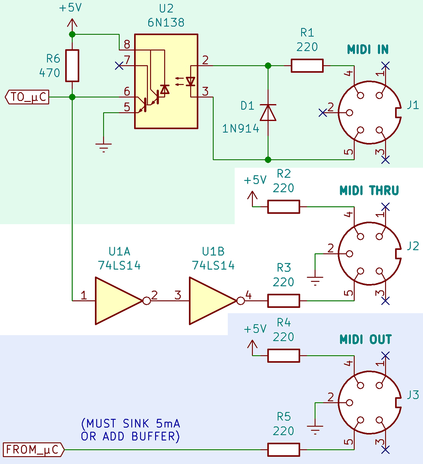
Standard MIDI circuit
The MIDI circuit is a current loop, 5 mA. Sending 1s and 0s is done with changes in current rather than voltage. Logic 0 is current ON.
One output drives one (and only one) input.
MIDI THRU is wired to IN and sends along whatever is received
To avoid grounding loops and subsequent data errors, the input is opto-isolated. It requires less than 5 mA to turn on.
Also to avoid ground loops, pin 2 of the MIDI In connector must be left floating (not connected to ground).
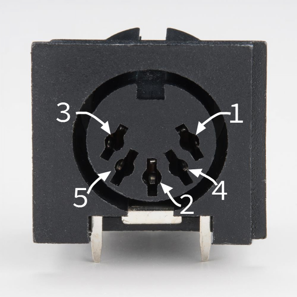
The standard connector used for MIDI is a 5 pin DIN.
Cables are shielded twisted pair, with the shield connecting pin 2 at both ends. The pair is pins 4 and 5. Pins 1 and 3 are not used, and should be left unconnected.
Group loops
Every MIDI connection must be optically isolated in order to avoid ground loops. Without optical isolation, a MIDI cable can create a ground loop by making an additional connection between devices that are already grounded together via a wall outlet, introducing 50 or 60 Hz hum.
MIDI plug and cable wiring
Cable
In a MIDI cable, pin 2 is always connected to the cable shield.
| First connector | Cable | Second connector |
|---|---|---|
| Pin 1 | not connected | Pin 1 |
| Pin 2 | Shield | Pin 2 |
| Pin 3 | not connected | Pin 3 |
| Pin 4 | +5V (Voltage Reference) | Pin 4 |
| Pin 5 | Data | Pin 5 |
DIN connector
In a MIDI DIN Input connector, pin 2 must be left floating (not connected).
| DIN In | Din Thru | DIN Out | ||
|---|---|---|---|---|
| Pin 1 | not connected | not connected | not connected | |
| Pin 2 | not connected | Shield | Shield | |
| Pin 3 | not connected | not connected | not connected | |
| Pin 4 | +5V (Voltage Reference) | +5V | +5V | This is the current source. This signal is held at +5V by the sending device so is also called the “hot” connection. |
| Pin 5 | Data | Data | Data | This is the current sink. The sending device switches between connecting this to ground (so a current can flow) and holding it at +5V or disconnecting it (so no current can flow). |